Drl Controller Wiring Diagram
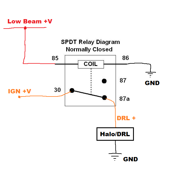
Connecting the +ve from the sidelights to pin 85 of that relay will bring the driving or fog lamps on whenever the sidelights are on, this will contravene vehicle lighting regulations and make the care illegal. Led lights create a uniform projection that that ensures maximum output and visibility making leds highly efficient.

Wiring Diagram For Led Daytime Running Lights schematic
The writers of drl controller wiring diagram have made all reasonable attempts to offer latest and precise information and facts for the readers of this publication.

Drl controller wiring diagram. Using a 30 amp spdt relay, connect terminal #87 to constant 12 volts positive with a fuse rated to the sum of the additional accessories you've added and the components you need to turn on. Wiring diagram for drl alternator has three adapter. Does anyone have the wiring diagram for the drivers side led headlight housing?
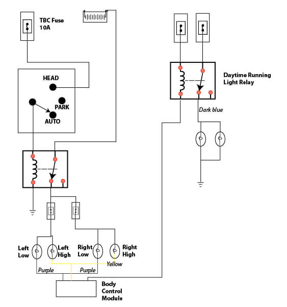
The third wire assuming it's intended for a +ve connection to dim the drl. Unlike many other headlight systems the normal headlights and drl lights are two separate systems but they re both controlled by the body control. It controls the operation of both front directional signal lamps.
Here are two diagrams showing you how to connect them using a relay. One of the key features of our headlights is to have the ability to run the drl strips in the day without having to activate any of your lighting controls manually. Lights will have to be cut on/off manually via the app.
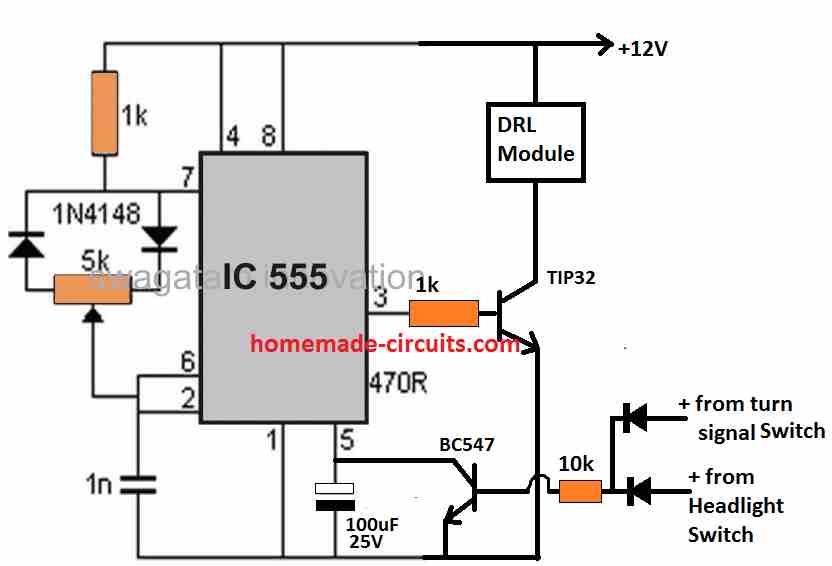
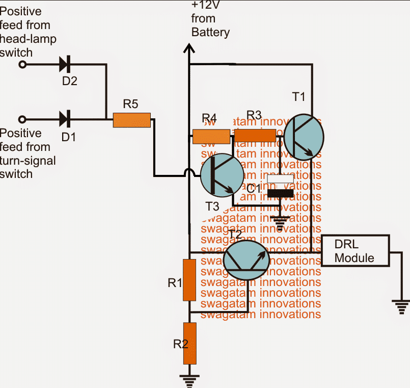
E eltaco ram guru joined feb 9, 2020 messages 541 reaction score 534 The resistance is 40 ohms. 2 shows the circuit diagram of the daytime running lights controller.
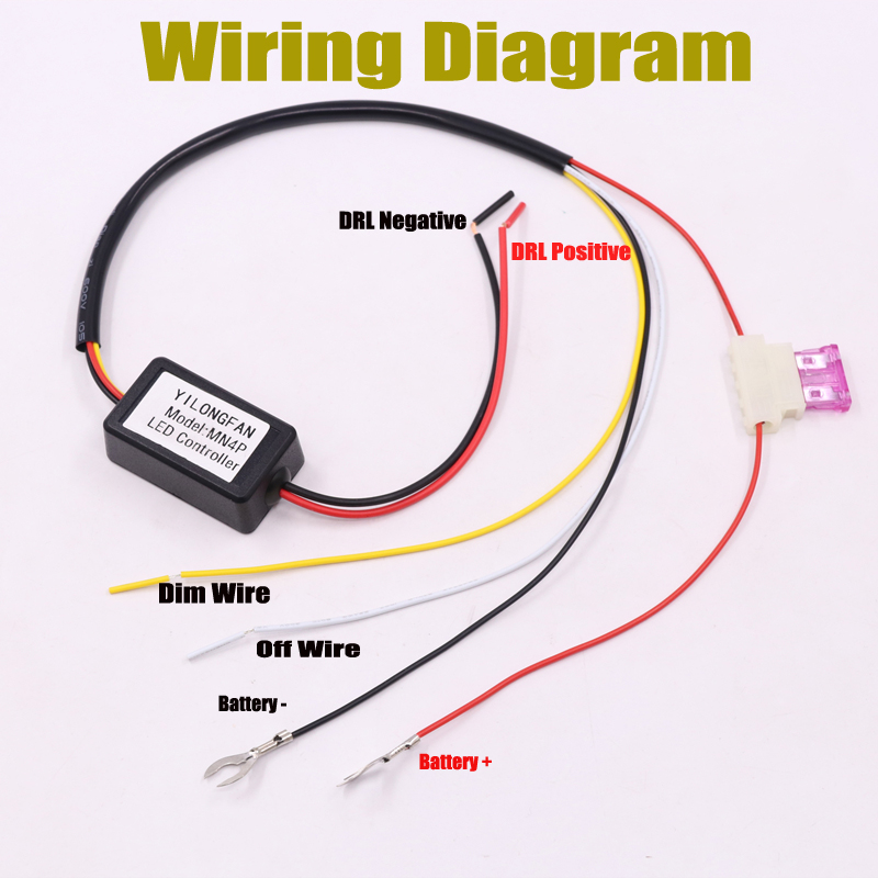
What's a drl or day time running light device: Red is main power wire "it must be connected directly to the battery positive terminal" you will have to extend that wire as it won't reach the battery simply use proper gauge wiring and run a wire from the battery to the positive wire of the drl. Please note that this diagram.
I'm looking to tap into the high beam and drl wires to control the two modes of my aftermarket led light bar. There are seven wires that come out of the circuit. If you temporarily connect that third wire to the positive lead of the drl, presumably the drl should then dim.
Download full version pdf for drl controller wiring diagram using the link below: The creators will not be held accountable for any unintentional flaws or omissions that may be found. This will allow you to control the lights at all times even if car is off.
The blue wire from the adapter is supplied to the expander. Power windows page a 2 3. A drl is a safety car lighting device specifically assigned to moving vehicles for increasing the conspicuity of the vehicle during day time, especially when the daylight is accompanied with fog or during dull overcast days.it is normally fixed just beside the headlamps on either sides.
A number of products within our range include daytime running lights (drls), below is a diagram for customers interested in wiring them up via a relay, to allow them to turn off when the low beam headlights are turned on. If you have a wiring diagram for the car, this will help you identify these wires. Yes you can wire the controller two ways:
It is built around timer ne555 (ic1), mosfet 60nf06 (irf1), 12v, 1c/o relay (rl1), drls and a few other components. 2) connect the red wire to a permanent live 3) find a suitable earth point near the drl box for the black wire. You can wire the controller to a drl fuse or parking light.
The way to do this is by wiring the harness that is included with your headlights.depending on the headlights feature you get, there will be two types of drl harness. For headlights with activation light and sequential. It is shown controlling driving lamps or fog lights.
Dec 14, #5.connecting additional devices to the remote turn on wire relay wiring diagram: 1) connect the harness to the drl's and feed all the wires up behind the grill so that you can mount the drl controller on the inside of the wing. Shop for drl controller on amazonus:
I'm planning to use these two wires or fuse taps as inputs to trigger my relays. Drl controller wiring diagram ebook title : Extender for these purposes is chosen with an open rectifier.
( recommended) you can wire controller straight to battery or constant power source: Additionally, it remains to connect the converter. Directly first contacts closed on the plate.
Daytime running lights controller detailed project available 3 interesting drl day time light circuits for your car homemade circuit projects creating a simple indicator sensitive all about schematic diagram of 15 scientific board universal led w vibration sensor enhance with this connection through 5 pin do it yourself installation on control unit frequently asked questions. In addition, any local auto electrician should be able to set this up for you if needed. 16.09.2018 16.09.2018 1 comments on wiring diagram for 5 pin relay for drl with turn signal wire we frequently get asked "should i install a relay with the lights?
Either way whatever you do to that relay in the diagram it won't affect the drl as there is no connection to any drl!
Drl Controller Circuit Diagram Wiring View and

DIY How to add daytime running lights (DRL) to a 2010
1993 Chevy 3500 Tail Light Wiring Diagram Wiring Diagram
WesternUltramountWiringDiagram RAUR.US

1995 Chevy Headlight Switch Wiring Diagram Wiring Sample

2d Lamp Wiring Diagram Wiring Diagram Schemas

1995 Chevy Headlight Switch Wiring Diagram Wiring Sample
on/off dimming automatic dimmer led daytime running light

1995 Chevy Headlight Switch Wiring Diagram Wiring Sample

Wiring Diagram For Drl Relay yazminahmed

Free Kenworth Wiring Diagram T800 Light Wiring Diagram
Drl Controller Circuit Diagram Irish Connections

Wiring Diagram Led Eye Wiring Diagram Schemas

Victron Inverter Wiring Diagram

96ChevyTruckWiringDiagram RAUR.US

1995 Chevy Headlight Switch Wiring Diagram Wiring Sample
drl wiring question G35Driver Infiniti G35 & G37 Forum
IR Remote control on off switch circuit Remote control

Make this DRL (Day Time Running Light) Circuit for Your Car


