Phase O Matic Wiring Diagram
Stop button feed wire sleeve is #t, other terminal goes to one side of the start button and daisy chains into the wiring back to the big box. Diagram rotary phase converter with idler motor diagram full version hd quality motor diagram diagramate mbreporter it from users.rcn.com this is just one of the solutions for you to be successful.
32 Phase O Matic Wiring Diagram Free Wiring Diagram Source

Motor speed is not changed.

Phase o matic wiring diagram. It shows the components of the circuit as simplified shapes, and the power as well as signal links in between the devices. Get free phase a matic wiring diagram components of the circuit as simplified shapes, and the power as. If you are trying to build one yourself, the following diagrams and videos may.
It shows the page 13/27. List all motors on the system by size and type of use. Estimate the size you need by following these three easy steps:
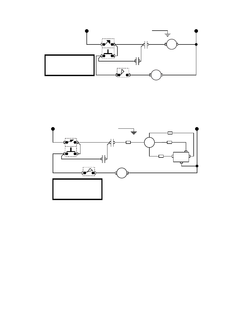
The third wire of the converter is connected to t2 = b, with the t2/b wire to the starter having been disconnected. Assortment of phase o matic wiring diagram. Pam 300hd 1 3 hp 220 vac phase a matic phase.
Find the model on the chart that correlates to the total system horse power and largest motor. Find the model on the chart that correlates to the total system horse power and largest motor. This is not true today.
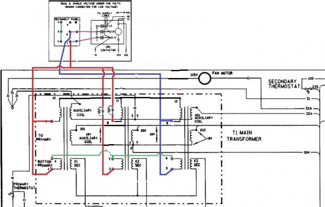
Technical documents · installation guides · wiring diagrams · cutout templates · compliance documents · live chat · email · 978.988.9665. My #3 wire corresponds to ll3 feed from fuse sfu2 to toggle switches on the diagram. Estimate the size you need by following these three easy steps:
Static converters on phase a matic inc converter pam series instruction sheet how does work napcco rotary installation practical machinist largest manufacturing technology forum the web caution read following carefully before attempting phaseconverter 3 for vs variable frequency drives making with. Is a leading supplier of phase converters, voltage stabilizers, and transformers for every industry including: Such a converter would be connected directly to the motor's t1, t2 and t3 leads, where.
To the idler motor as per method no. About press copyright contact us creators advertise developers terms privacy policy & safety how youtube works test new features press copyright contact us creators. T3 = c = l2, and.
1 will produce approximately 2/3 rated horsepower. Phase o matic wiring diagram : List all motors on the system by size and type of use.
Restaurant, clothing, marine & nautical, hvac refrigeration, hotel, medical, automotive, cnc, metal & woodworking fabrication, agriculture, welding, and a host of other home shop and commercial applications. Phase a matic wiring diagram written by 06 poe saturday, july 24, 2021 add comment edit. 1 static phase converter instruction sheet the minimum range may then be started and can usually be 9.
A wiring diagram is a simplified standard photographic representation of an electrical circuit. Assortment of phase o matic wiring diagram. T1 = a = l1, and.
Electricity 101 basic fundamentals industrial controls. Ice o matic cd300 user manual. The sideway diagram as shown here.
Surpluscenter com / sitiaida december 27, 2021 use the manual release only when the gate is not moving. Work out the size you need: Bunn o matic commercial coffee grinder.
A wiring diagram is a simplified standard photographic representation of an electrical circuit. Do not connect 230v power or a ground or neutral wire from the utility to the b terminal of the converter as the resulting dead Easy install of a phase a matic pam 600hd static phase converter to run a 3 phase mill on single phase 220 voltsubscribe for more.
Reel o matic measuring pultrusion coiling hoses by. This method is inexpensive, the most popular, provides excellent results on most machines tools and numerous other uses. 3 4 hp to 1 1 2 hp phase converter.
Add up the horse power rating of each motor to get the total system horse power. Phase a matic wiring diagram.mount converter upright with the junction box on the top. Bunn nhb owner s manual use and care.
Work out the size you need: The sideways diagram as shown here is to suit the illustration space only. View all of our static phase converter products here:
Here are some wiring diagrams of rotary phase converters (rpc) that i found on the web. Add up the horse power rating of each motor to get the total system horse power. Phase a matic static converter wiring diagram.
Wires on other sides of toggle switches are marked #6, #7, #0 and #1 in same order.

Ronk Phase Converter Wiring Diagram Complete Wiring Schemas
32 Phase O Matic Wiring Diagram Free Wiring Diagram Source


32 Phase O Matic Wiring Diagram Free Wiring Diagram Source

Ronk Phase Converter Wiring Diagram Complete Wiring Schemas

Static Converters On PhaseAMatic, Inc.
Lister Generator Wiring Diagram

Lister Generator Wiring Diagram
Miller 115/240 Wiring Diagram

Technocat's TechTalk Saving wasted "Phantom Power " drawn

Phase O Matic Wiring Diagram Free Wiring Diagram
Phase O Matic Wiring Diagram Diagram Resource Gallery

32 Phase O Matic Wiring Diagram Free Wiring Diagram Source


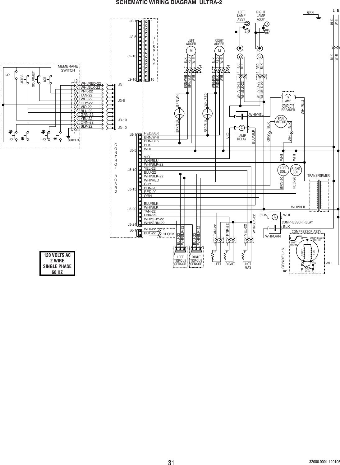
Bunn HC3 SCHEMATIC WIRING DIAGRAM HCA2, & HCA3
Phase O Matic Wiring Diagram General Wiring Diagram
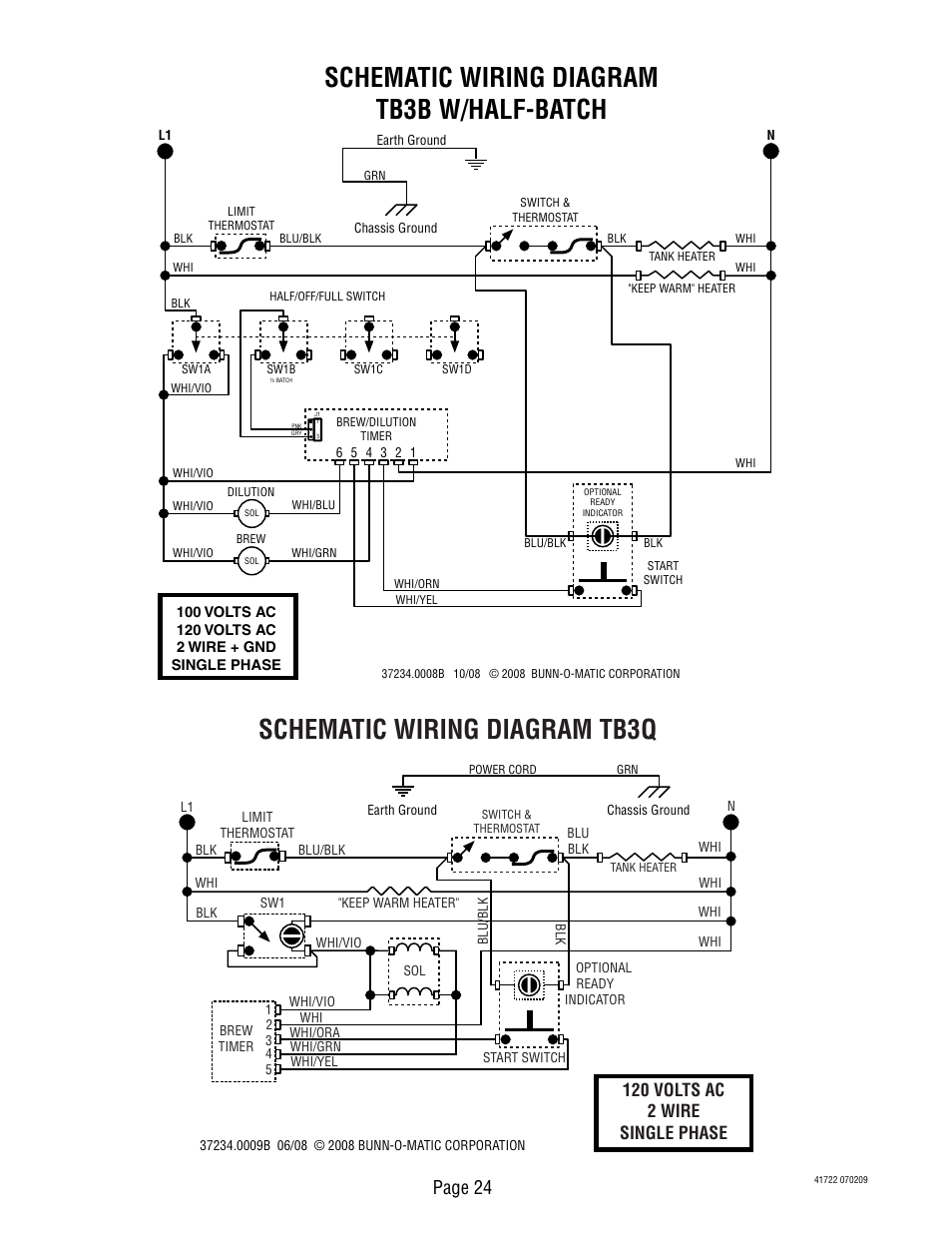
Schematic wiring diagram tb3b w/halfbatch, Schematic
Phase O Matic Wiring Diagram General Wiring Diagram
32 Phase O Matic Wiring Diagram Free Wiring Diagram Source

Phase A Matic Static Converter Wiring Diagram Wiring Diagram
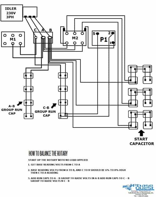
Wiring Diagrams Phase Quest Inc.Phase Quest Inc.

